Steering wheel button control adapter for Mercedes ACV SWC 42XMC013-0
steering wheel adapter for Mercedes CLS-class (W219) (10/04->06/08), E-class (W211) (03/02->02/08) a SLK-class (R171) (03/04->03/08)
More about the product
More about the product
We will help you with your purchase
- You can return the goods to us within 14 days
Steering wheel button control adapter for Mercedes ACV SWC 42XMC013-0
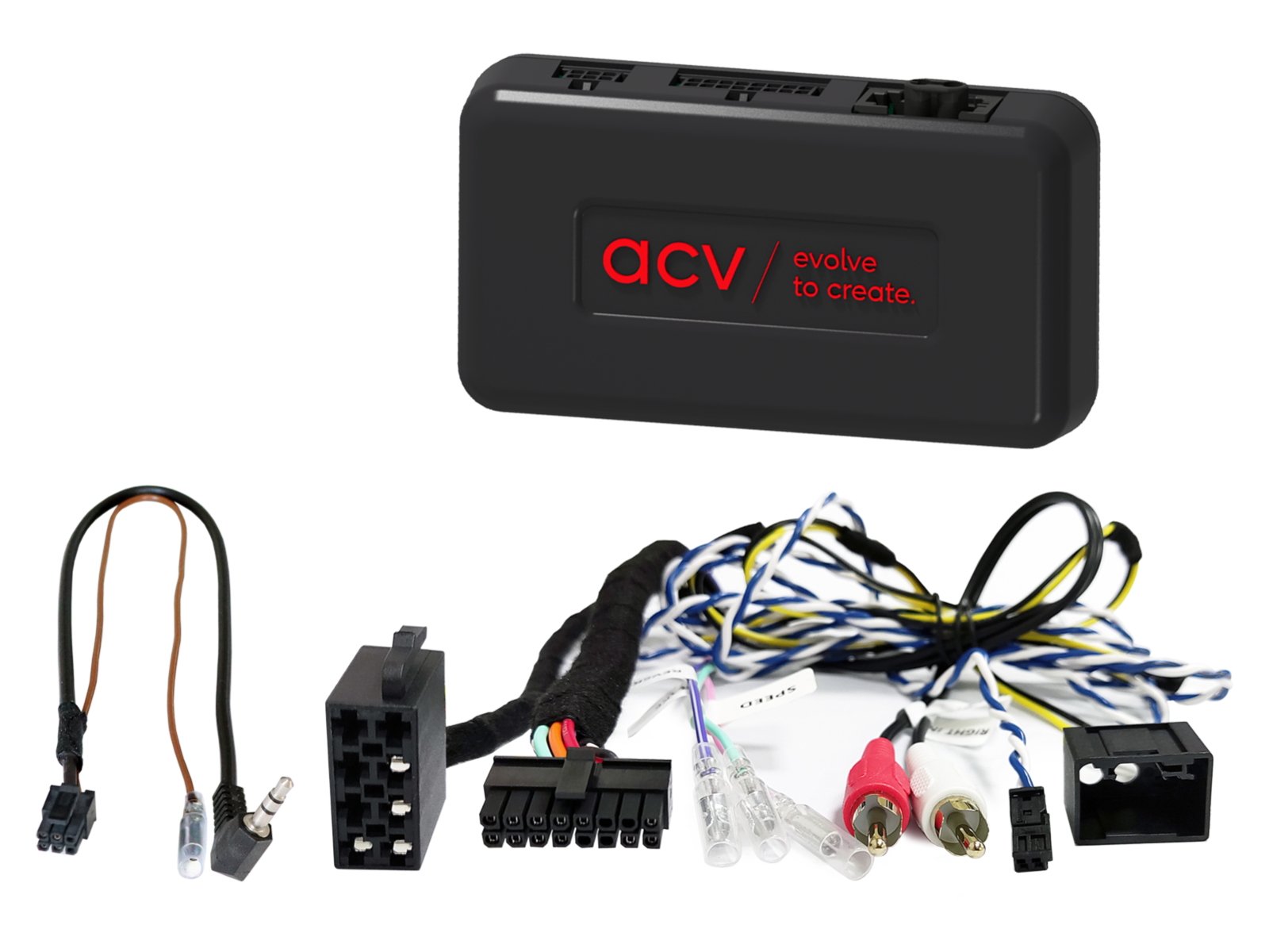
Retain the original steering wheel radio control functions when replacing the factory radio with an aftermarket unit. Depending on the vehicle's equipment, the range of functions and the software of the newly installed head unit, some functions may be limited or replaced by others. Compare the displayed wiring connectors with the connectors in your vehicle and make sure they match both technically and visually. Check whether one of the listed OEM head units was originally installed. Before final installation, verify the vehicle functionality, system settings and proper operation of the steering wheel control (SWC).
Intended for vehicles
- Mercedes CLS-class (W219) (10/2004 -> 06/2008)
- Mercedes E-class (W211) (03/2002 -> 02/2008 — glove box electric function not supported)
- Mercedes SLK-class (R171) (03/2004 -> 03/2008)
CAN Bus Information
Connectors and Power Supply:
- Connector: 2 Pin Mercedes.
- Connector: 2 Pin CAN Bus distributor.
- Connector: OEM amplifier system MOST > RCA (male) red / white.
Compatibility and limitations:
- Vehicles with 2-DIN Audio 50 APS Comand NTG2 / NTG2.5 OEM Sat Nav.
- Vehicles with Harman Kardon OEM amplifier system.
- Vehicles with MOST25 OEM amplifier system.
- Vehicles with Audiogateway.
- Vehicles without Comand 2.0 / 2.5 OEM Sat Nav and without D2B Optical Bus.
- Fader function not supported.
- Time setting not supported – if possible, recode vehicle to Audio 20 OEM HU.
- Antenna extension cable not included.
- In some cases noise may occur during power on/off.
Signals and output load:
- Red: +12 V ignition (Klemme 15).
- Orange: +12 V illumination (Klemme 58).
- Purple / white: +12 V reverse signal.
- Pink: speed signal (Speed pulse).
- Green: GND parking brake signal.
- Max. output load: 250 mA. Above this use relay – 1 relay min. 75 Ω, 2 relays min. 150 Ω.
Important Additional Information
- OEM units (CD changer / TV tuner / phone module) must be removed from the MOST loop if required: MOST optical connector: 771000-2100, MOST optical loop (female): 771000-2001.
- To fully activate the adapter, a connection cable must be ordered.
Optional accessories
- Antenna extension cable Fakra (male) > Fakra (female) 200 cm – 1524-200.
- Antenna extension cable Fakra (male) > Fakra (female) 500 cm ROKA – 1524-500-1.
- Antenna adapter Fakra Z (male) > DIN (male) passive LEONI / ROKA – 1524-01-1.
General Installation Instructions
Verification Before Installation:
- Check all control functions and vehicle settings using the original OEM HU.
- Disconnect the original radio (OEM HU) in a voltage-free condition.
- Check all interface connections – without power.
Connection and Installation Sequence:
- Set and check the HW configuration of the interface – without power.
- Check the configuration of the HU connection cable – without power.
- Connect the cable to the HU according to the aftermarket device manual.
- Connect the remaining wires according to the device manual.
- Connect the complete installation to the vehicle – connect the main power supply last.
- Perform the software configuration of the interface according to the product description or manual.
- Configure the aftermarket HU (steering wheel control, camera, handsfree, antenna power etc.).
- Perform a functional test of steering wheel control and vehicle communication.
Configuration Changes:
- All changes must be carried out without power.
- After changes repeat steps 5 to 8 above.
In Case of Failure:
- Reinstall the original OEM HU.
- Start the original unit.
- Initiate CAN Bus shutdown.
- Check the HW configuration of the interface.
- After CAN Bus shutdown repeat steps 5 and 6.
When Modifying Wiring:
- Installation and modifications may only be carried out by professionally trained personnel.
- All changes must be verified before connection regarding manufacturer approval or impact on vehicle warranty.
- All modifications must be verified by measurement and comparison with the vehicle wiring diagram.
- Modifications are carried out at your own responsibility without guarantee of functionality.
- Modifications are performed at your own risk without guarantee against damage to the vehicle, device or interface.
- Modifications of pre-installed wiring may result in loss of product warranty.
| Catalog number | 42XMC013-0 |
| Brand | ACV |
| Links | Official web presentation |
Evaluation
- Car radios and accessories Steering wheel button control adapters Mercedes-Benz steering wheel adapters
- Car radios and accessories Steering wheel button control adapters Mercedes-Benz steering wheel adapters Mercedes CLS steering wheel adapters
- Car radios and accessories Steering wheel button control adapters Mercedes-Benz steering wheel adapters Mercedes SLK steering wheel adapters
- Car radios and accessories Steering wheel button control adapters Mercedes-Benz steering wheel adapters Mercedes E_Class steering wheel adapters
- ACV
ask us